

The mechanical or electrical defects of load cells lead to incorrect operation of weighing systems or complete breaking. Fortunately, most problems can be identified with a few simple tests described in this text.
Before the test, need to be sure, that the below conditionals are performed:
- Use a regulated power supply. If the voltage of the power supply floats, talking about stable sensor readings isn’t possible. A voltage of 5 or 10 volts is usually used. Be sure to refer to the load cell specification for the required drive voltage.
- Obligatory to use a high-precision multimeter that has at least 2 numbers after the comma in the millivolt (mV) measurement. Many shop multimeters do not have a sufficiently high sensitivity.
Visual inspection
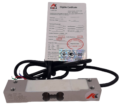
The first step for checking load-cell it’s to do a visual inspection. Often, a problem can be identified before measurements.
Pay attention to the next:
- Violation of the form or deformation of any part of the load cell indicates that unacceptable influences have been made, most likely exceeding the maximum allowable load, shock loading, or side loading. In this case, a complete replacement of the sensor is recommended.
- Damaged welding: welding seams shouldn’t have cracks, deep potholes, or other anomalies. Violation of the integrity of the welding seam can lead to the ingress of moisture and dust into the load cell.
- Lots of rust: a small amount of rust on the outside of the load cell case does not significantly affect the efficiency of the load cell, but rust may indicate possible moisture damage to the interior. This problem can be avoided by using stainless steel load cells for wet environments. Be sure to carefully inspect the seals to see if there are any signs of rust.
- Excessive corrosion: the influence of chemicals, powder, gas, or liquid can corrode the load cell case and its electrical components. Unlike rust, chemical corrosion can form even in stainless steel load cells. As with rust, be sure to inspect the case to see if there are any signs of damage.
- Cable damage. Cable of load cell needs to be checked along its entire length, from the place, where it connects with the sensor. Damaged or broken cable can lead to many problems.
Press test
Press test can be done by observing the readings of the weight indicator, lightly knocking the sensor with a screwdriver handle or rubber hammer (never use a hammer or other metal object), adjust the impact force based on the load limit rating of the sensor.
If the load cell is already disconnected from the indicator, this test can be done with a multimeter when check zero balance.
Zero balance of load cell
Zero balance (expressed as a percentage of rated power) is the value of the output signal of the load cell with a nominal supply voltage and no load.
- Disconnect the load cell from the indicator.
- Be sure, that sensor without weigh load and supply wires is connected to the power source that supplies the recommended power for this sensor, as specified in the datasheet (this voltage can be applied from the weighing instrument, leaving only the appropriate wires connected).
- Connect a multimeter to the signal wires of the load cell and measure it.
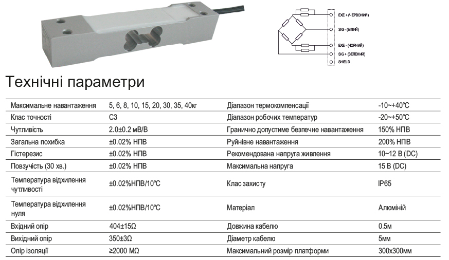
- Note: Load cells have a parameter called “Operating Transmission Factor (RCP)”, indicated in the passport in units of mV to V; power supply and output signal in V. In case when using supply 5V, load cell which has RCP equal 2mV/V, the issue on signal 10 mV with a full load on the sensor.
- A zero-balance deviation exceeding the tolerance identified in load cell specification (usually from 1%), informed that the load cell is damaged.
Example: based on the previous information: if supply 5V and RCP 2mV/V with a full load on the sensor, the voltage on the signal wires will be 5V x 2mV/V = 10 mV. Therefore, without load, the output voltage must be more than 1 percent of 10 mV, and the output will be no more than 0.1 mV.
Checking of bridge balance
Measure with a multimeter the resistance across the arms of the sensor’s resistive bridge.
- Make sure that the load cell is disconnected from the power circuit and doesn’t affect it.
- Do wires shorter by twisting them.
- Measure and write the resistance between the signal output and the negative power terminal.
- Measure and write the resistance between the signal output and the positive power terminal.
- Both readings usually must be different no more than 1 Om from each other. A difference of more than 1 Om almost always indicates on sensor defect.
Input and output load cell resistance
Use a multimeter (resistance measurement mode) to compare the bridge strain gauge’s input and output resistance.
- For measuring the resistance of the bridge, place the multimeter leads between the +Exc and -Exc terminals.
- For measuring the input bridge resistance, place the multimeter leads between terminals + Sig and -Sig.
- Both readings must conform to values specified in the load cell specification.
Bridge resistance
Above method, do the next resistance measurements:
- between +Exc and +Sig
- between -Exc and +Sig
- between +Exc and -Sig
- between -Exc and -Sig
In most cases, these readings should not differ by more than 1 Om, but old models of load cells can be exceptions.
For a more accurate diagnostic is recommended to contact either the service center or the load cell manufacturer.